ANTENNAS
FROM A DIFFERENT PERSPECTIVE
PAGE INDEX
Introduction to the information on this page and scope of discussion.
How a ground plane antenna works, what it does and why the ground plane is there. (Read BASICS FIRST)
How a simple resonant dipole works, what is the difference between that and a ground plane. (Read BASICS FIRST)
BASICS
KEEP IT SIMPLE - APOLOGIES FOR INACCURACY
There are several definitions and several ways of measuring everything. This page tries to keep things simple and uses compromise definitions.
A FEW BASIC CONCEPTS
1) For any current to occur, it must be induced by an electric or magnetic field somewhere along it's length or pushed by a potential difference between two points somewhere along it's length.
2) Magnetic field fluctuations only influence things orthogonal to it. The magnetic field fluctuations in a centre fed dipole with an orthogonal feedline are orthogonal to both.
3) Electric fields influence any conductor near it. They influence both parallel and orthogonal conductors.
REFERENCE DIPOLE - NO SUCH THING
Often it is said, "the (radiating) resistance of a half wave dipole is 75Ω." This is true only for a theoretical, infinitely thin, superconducting antenna such that the velocity factor is 100% and there is zero resistance in the radiating conductor. No such thing exists anywhere in the known universe as far as I am aware. Many also presume the radiating resistance of any half wave dipole is also so close to 75Ω, any difference doesn't matter. This is a totally false presumption.
It takes very little change in length to change the radiating resistance significantly. The capacitance and inductance will also change with length. As mentioned under Transmission Lines, it is impossible to terminate a 50Ω transmission line with anything other than a 50Ω resistor without creating reactance. If you have a length of 50Ω coax greater than ¼λ and the SWR is 1:1, the feed-point resistance (end of the coax) can not be anything other than 50Ω resistive.
RADIATING AND FEED POINT RESISTANCE - USE OF TERMS
There are several definitions for radiating resistance. Voltages and currents can be measured or calculated along the length of the radiator and the radiating resistance calculated from that. It is NOT necessarily the same as feed-point resistance but for the ease of discussion, this page will use radiating and feed-point resistance (reactance) interchangeably as the resistance (reactance) at the interchange between the feedline and antenna even though this might not be strictly correct.
SHORT REMINDER OF TRANSMISSION LINE CHARACTERISTICS
Consider having two parallel conductors with one end but infinite in length (so they will not have another end). If a voltage is applied between the conductors (at the end), current will flow. This is because both conductors start off in a neutral state and need either more or less electrons (or any charge carrier) to be at the same potential as the source.
This current will continue to flow forever because the length of the conductors is infinite. The current that flows will be determined by several factors including the thickness of the conductors, the distance between them and the dielectric constant of the separating material.
There will be a certain voltage and there will be a fixed current so an equivalent resistance (a type of impedance) can be worked out from the two.
The characteristic impedance of a transmission line is the value of resistor into which the same current will flow as an infinite length of transmission line.
For losses line (superconductors), this will be frequency independant. Once the actual resistance of the conductor is added, increasing resistance at increasing fequencies means the characteristic impedance of the transmission line will increase. For most purposes, this can be ignored although it should be remembered that at 1GHz the resistance of the wire, used to make the line, may be 1000 times or more the resistance at DC. (Depending on thickness.)
Given this definition, if the infinite length is cut somewhere and replaced with an equivalent resistor, the end of the transmission line will behave exactly the same as if there is an infinite length of transmission line still attached.
Properly terminated transmission lines can therefore be any length and maintain the same characteristics.
If you require a multiple of a half wave length of coax to get an antenna working, it is simply a lousy antenna.
WHERE ARE THE CURRENTS IN A CONDUCTOR - SKIN EFFECT
The skin effect in a single conductor is caused by eddy currents within the conductor. At DC, current is conducted equally through the entire cross section of the conductor. This is because the magnetic field is static. Faraday's Law of induction says the emf induced is proportional to the rate of change of magnetic flux, not the amount of flux. There can be millions of amps and a strong magnetic field but if it isn't changing, no eddys will result meaning the entire cross section of conductor will conduct.
At low frequencies, all that happens is the probability an electron will move at the centre of the conductor is reduced compared to one on the outside. The higher the frequency, the greater the difference in probability but this probability is NEVER zero. The conducting channel is not a definite thickness but an increasing probability a charge carrier will move closer to the outside surface of the conductor.
When skin thickness is quoted, it is the depth (into the conductor) where there is a probablity of greater than about 0.37 an electron will move. At 50Hz for example, the skin-channel thickness of copper is about 9m. This means there is a 63% probability an electron will move in the direction of the current within this 9mm and about a 37% chance one will move at greater than 9mm from the surface.
This means the higher the frequency, the higher the "rate of change" (the quicker the change) of magnetic flux so the more eddy effect and therefore the higher the resistance of the wire.
SKIN EFFECT IN COAX OUTER
The inner conductor of coax produces a magnetic field around it. Working currents in the outer, equal and opposite in direction, also produce an opposite magnetic field. These balance out on the inside of the coax outer so currents can flow there. No change (or a cancelled one) means no eddys. Other currents in the coax outer (not opposite and the same as the inner) will produce the eddys described above and will flow on the coax outer.
Some diagrams showing currents flowing up the inner and separating at the top give a totally false impression. For there to be currents other than working currents, something must induce them to flow. Different forward and return impedances cause a voltage difference which is what drives currents on the outside of the coax.
GROUND PLANE ANTENNA
WHERE IS THE RESISTANCE
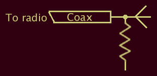
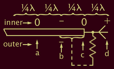
| Consider first a quarter wave radiator just connected directly to the coax centre and the coax outer left "dangling in the wind" LEFT. This will radiate but where is the resistance seen, that is, what is the other end of the "radiating" resistor connected to. Although the radiating resistor is not a physical component, it consumes power and behaves like one. RIGHT Waves travelling along the coax inner will emerge from the coax at point "c" and be reflected at point "d". Since "d" is ¼λ away from "c", it will be ¼Π out of phase. Take a point of time when "c" is at zero volts, and the voltage is falling (at "c"). Point "d" will be at maximum positive. |
|
The electrical field between "c" and "d" will be attracting and repelling electrons in the coax outer between "b" and "c". The electrons at "b" are half a wave length away from "d" and will still be reacting to the previous -ve condition at "d". That is, "b" and "d" are ½λ away from each other and are therefore Π/2 out of phase.
The induced current in the coax outer will therefore be in phase with the coax inner. Currents in phase are called common mode currents. The first ¼λ of coax outer is acting as half of the antenna. In antiphase to driven working currents. In addition, the induced currents between "b" and "c" are also inducing further common mode currents between "a" and "b" and so forth all the way back to the radio.
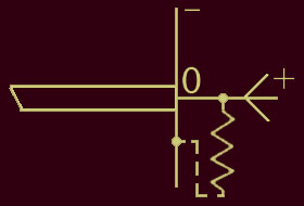
The only way this can work is by having an odd multiple of ¼λ from point "a" back to the radio. A ¼λ wave section (or odd multiple) will match a maximum impedance to a minimum impedance or vice versa. The length of coax in this situation therefore needs to be an exact multiple of ½λ. This situation is far from ideal. It can be made to work with any length of coax by placing a choke at point "b" but this is not the best solution. The influence of the electric field in the radiator extends well past "b" towards "a" and beyond. This is only a partial solution. Placing a coaxial choke at "c" wouldn't help at all because the radiator would still be working against the coax outer from "c" to "b". A better way is to simply add a ground plane RIGHT. This gives the radiator something to work against, that is, the "radiating" resistor is connected to a pseudo-ground. Any currents induced in the outer will now be of the same sense as the inner. That is, WORKING CURRENTS are induced into the coax outer from the ground plane in an oposite sense to those induced by the radiator. This is exactly what we want and so ANY LENGTH of coax can be used because the end of the coax behaves like a 50Ω resistor. |
|
HALF WAVE DIPOLE - ANOTHER WAY OF LOOKING AT IT
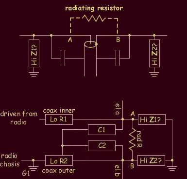
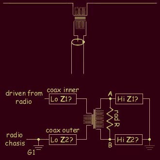
A half wave dipole connected to the end of a piece of coax looks similar to the top diagram at right. The electrical field in the left hand element will induce an equivalent electric field in the right and a radiating resistance will be seen between the two radiators as shown. In addition, unless the dipole is miles up in the air (or in space), both will have some sort of connection to the ground which will appear inductive or capacitive depending on how far from the ground each element is. In extremely humid air or when its raining heavily, it may even show a resistive component. In any case, the impedance to the ground, in normal circumstances, from both elements, will usually be higher than the radiating resistance which, in turn, will be higher than the feedline impedance. (Hopefully) The bottom diagram shows an equivalent circuit. Notice there are 3 paths to ground for the signal driven by the radio:- 1) Radio → LoZ1 → HiZ1 → Gnd The first two paths are through high impedances so only small currents will flow but only one path includes the coax outer. This means the currents through the first two paths will be conducted by the coax inner only. Because the HiZ paths are mostly capacitive or inductive, they won't consume power and the system will work quite well but the different impedances for the forward (A to gnd) and return (B to gnd) paths will allow the coax outer to act as part of the antenna. |
|
ATTEMPTED SOLUTION
One attempt at solving the problem is shown at right. Isolating the antenna means exactly the same currents MUST flow on both the coax inner and coax outer. |
|

All text and images on this site are Copyright to John Langsford (vk5ajl).
You may provide links on other sites or use the information and pictures for your own personal use.
You may use the text or images for redisplay or quotation provided you acknowledge the source ie. vk5ajl.com.
I think that's pretty fair, don't you?